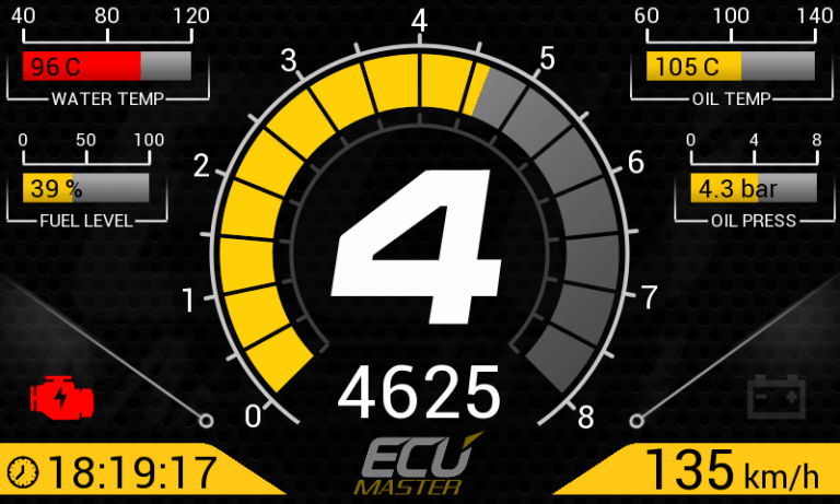
We are proud to announce the new ECUMASTER Racing Dash family of products. We designed the ADU5 and ADU7 in response to market demand for a cost-effective dash display with logging capabilities. Our specific goal was to create a fully customizable, feature-rich, quality solution for competitive drivers. We consulted professional drivers and race engineers and designed the ADU to exceed their requirements.
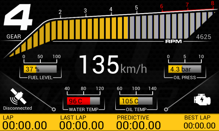
Above all, the ADU is designed to display all critical information in an easy to read manner, along with a comprehensive strategy for displaying alarms.
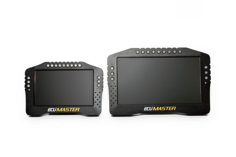
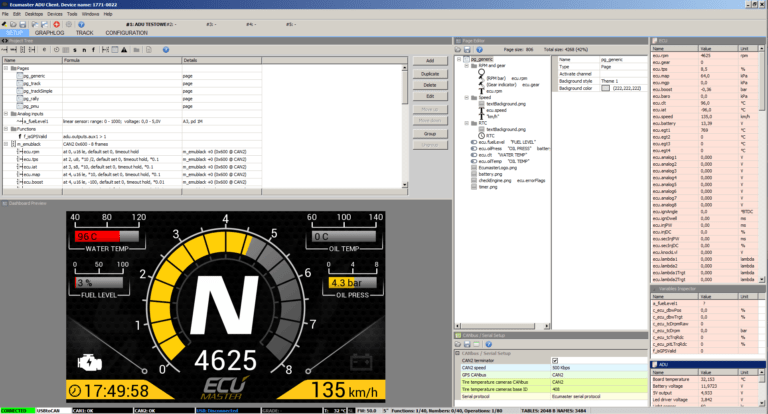
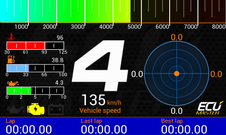
Our Advanced Display Units are available in 5” and 7” versions. Both versions feature high resolution, high visibility anti-glare screens, guaranteeing perfect visibility in any lighting conditions. The ADU comes with multiple pre-configured pages, which can be customized by the end user to display data required at every race stage (e.g. practice, qualification, race, troubleshooting, etc.). Pages may be changed manually or automatically (based on defined conditions). Each channel displayed on a page (gauges, icons, texts, etc.) can be easily modified in real time using user-friendly Windows based software. Our comprehensive overlay system facilitates a multiple page display for important data (e.g. low oil pressure, best lap, etc.) independent of the actual page displayed.
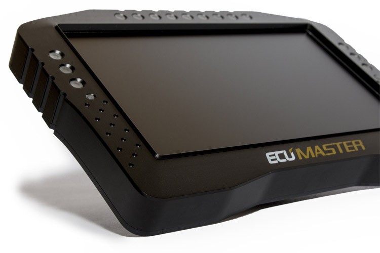
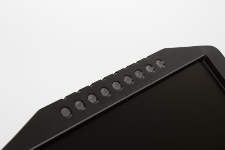
The ADU is also equipped with 15 ultra-bright RGB LEDs which can be used as an advanced gear-depended shift light and can be modified by user-defined logic (for alarms, low fuel level, etc.).
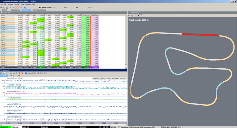
Using IR beacons or a GPS system, the dash turns into a powerful lap timer with a predictive timing function. By selecting the Qualification page, you enable a “Qualification Mode” which uses advanced predictive lap timing based on an automatically updated “best” reference lap.
User configurable timers can be adjusted for additional functionality (pit stop timer, etc.). The ADU also supports thermal cameras for monitoring brake discs or tyre temperatures (up to 16 points per tyre).
Communication with other devices in the car is provided via two built-in, independent CAN-BUS communication ports. CAN templates are provided for most popular ECUs, and are fully configurable, allowing you to connect our hardware to virtually any engine management system.
To ensure that all features work seamlessly, our device is based on a 32-bit automotive controller paired with a state of the art graphics processor. This combination provides the perfect working environment for any engineer or driver and guarantees anti-aliased, high-quality graphics at 50 frames per second.
For further data analysis, data channels can be logged to a USB Flash drive with a frequency of up to 500Hz.
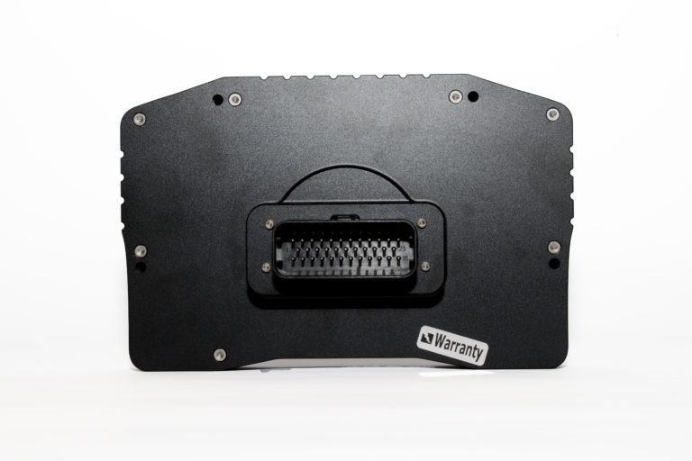
All of these “Must Have” features and more are housed in a rugged, specially CNC machined, black anodized enclosure.
Free, easy to install firmware upgrades further improve system capabilities (e.g. new strategies, trigger patterns, CAN data streams).
Supported ECUs
- AEM
- Autronic SM-4
- DTA Fast S series
- Ecumaster EMU CLASSIC serial
- Ecumaster EMU CLASSIC CAN
- Ecumaster EMU BLACK
- Ecumaster PMU
- Emtron
- EVO X
- Hondata Kpro
- Life Racing
- LINK ECU
- MaxxECU
- Megasquirt 2 & 3
- MoTeC M400,M600, M800
- MoTeC M1
- Pectel SQ-6
- Syvecs
- VI-PEC
- OBD 2 over CAN ecus
- Any ECU able to send data over CAN BUS
If your ECU is not listed above please send an email to tech@ecumaster.com. Our engineering team will work with you to create a configuration for your device.
Check the Application Notes page for wiring and configuration information specific to your ECU.
Download Files
ADU software package 50.1
Change log
ADU user manual English
ADU user manual Polish
ADU application notes
SPECIFICATION
GENERAL |
|
| Temperature range | AECQ100 GRADE1 (-40 to +85˚C) |
| Reverse battery protection | Yes, internal |
| Operating voltage | 6-22V, immunity to transients according to ISO 7637 |
| Enclosure | IP 60, custom CNC machined aluminum |
| Connectors | 1 x 35 positions, AMP Automotive connector |
| PC communication | CAN BUS – Ecumaster interface, Peak or Kvaser |
| Display Type | TFT 800×600 |
| Brightness of display | 5″ – 600 cd/m2, 7″ – 1000 cd/m2 |
INPUTS / OUTPUTS |
|
| Analogue inputs | 8 inputs, 10 bits, 0-5 V, software controlled pull-up/pull-down 10K resistor. Al analog inputs can be used as a switches |
| Digital inputs | 8 digital inputs, software controlled input sensitivity (VR, Hall), software controlled 4K7 pull-up resistors, used for engine speed sensors, Flex Fuel, wheel speeds, turbocharger shaft speed. All digital inputs can be used as switches |
| Outputs | 2 low side outputs (switch to ground), up to 2A, 1 analogue output (0-5V) 10 bits |
| +5V Output | Monitored 5V output for powering external sensors |
COMMUNICATION |
|
| CAN Interface | 2 x CAN2.0 A/B, 250, 500, 1000 Kbps |
| CAN streams | User-defined |
| Serial communication | RS232 Rx/Tx, AiM protocols, Ecumaster, Hondata Kpro, Autronic |
| USB | Used for logging to external USB memory |
OTHERS |
|
| Light Emitting Diodes | 15 ultra bright RGB LEDs |
| Accelerometer/gyroscope | 3D accelerometer + 3D gyroscope for the analysis of vehicle dynamics |
| Real-time clock | Yes, battery powered |
| Light sensor | Yes, for automatic correction of brightness |
| Temperature sensor | Yes, for monitoring device temperature |


